

Measure Power Inductor Using An Oscilloscope
Measure Power Inductor Using An Oscilloscope
Power inductors are widely used in electronic circuits, with varying quality. Now a simple test method is provided to test the saturation current and inductance value of the inductors. This provides a reference for engineers in testing, selection, and cost reduction.
Inductance is defined as UL=L*di/dt---->L = UL*dt/di, where UL is the voltage across the inductor. Based on the above principle and magnetic saturation law, the following is obtained:
1) The ratio of current to time in the normal operating region of the inductor is constant, i.e. the slope is a constant.
2) As the current through the inductor gradually increases, the inductor will gradually enter the saturation state, and the inductance value will gradually decrease. When the inductor is completely saturated, it will become a resistance with only the coil DC resistance (DCR). The current will rise linearly and reach the magnetic saturation state.
3) An oscilloscope can be used to measure the saturation current and inductance value of the inductor. The difference between the inductance value obtained and that obtained with an LCR bridge is very small. The measurement results of the saturation current are consistent with those obtained from current superposition testing.
Testing principle:

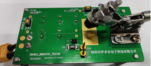
As shown in the figure, a regulated power supply is used to power the circuit, and a capacitor with a sufficiently large capacity is used to ensure that the voltage does not drop during discharge. The power-on switch is closed to charge the capacitor, and then opened. The TEST switch is closed to discharge the inductor and sampling resistor, with a high-precision R2: 0.05Ω used for the sampling resistor. The voltage across the sampling resistor is measured with an oscilloscope. The current through the inductor is calculated as I=V/0.05, with the inflection point corresponding to the voltage of the magnetic saturation current. Diode D1 filters out the reverse current from the inductor oscillation, resulting in a clearer waveform.
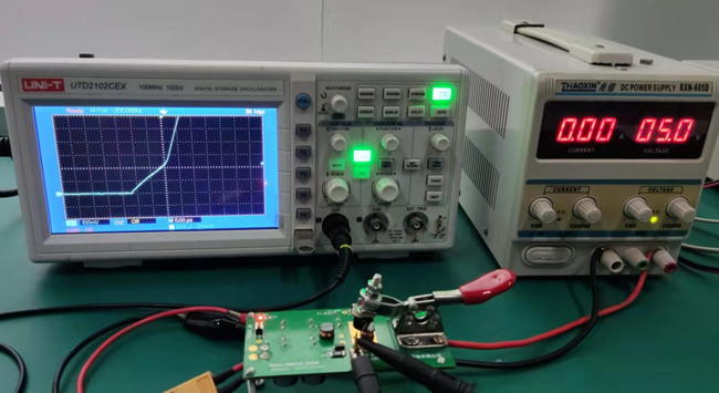
Experimental testing and verification:
Power supply: Zhaoxin RXN-605D
Oscilloscope: UNI-T UTD2102CEX
Test board: independently made by ENJOLE
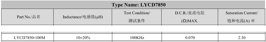
Test inductor: brand: Lunyou, LYCD5845-100M
Analysis of experimental resultsÔºö
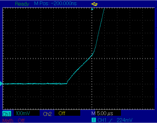
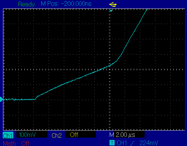
Saturation transition voltage: V=0.224V
Saturation current: Isat=V/R=0.224V/0.05Ω=4.48A
Inductance value calculation: L=UL*dt/di. Using the cursor function of the oscilloscope, L=(5V-0.224V)*10us/4.48A=10.66uH was obtained in the figure.
Checking the Lunyou inductor specification data sheet, the nominal inductance value is 10uH, which is basically consistent with the calculated value.
To further verify the accuracy of the device, a sample was tested on an LCR bridge instrument:
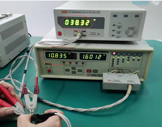
Test results: Inductance value L=10.835 DCR=38.32mΩ
Conclusion:
1) The proposed method for testing inductance is comparable to the test value of the LCR bridge, and the results of testing several samples separately are basically consistent, so this method can be used to calculate the inductance value.
2) The test value of the saturation current is much larger than the nominal value, indicating that the manufacturer has a large margin, and the actual test value can be used to evaluate the design, especially when the space is limited, and a smaller inductance can be selected to meet the design requirements.
3) The DCR DC resistance has a large margin compared to the conventional nominal value, indicating that the manufacturer's copper wire material is of good quality and also helpful for temperature rise current.
PreviousÔºöApplication of temperature rise current parameters for power inductor Next ÔºöNo